Regístrese ahora para una mejor cotización personalizada!

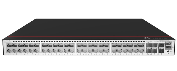
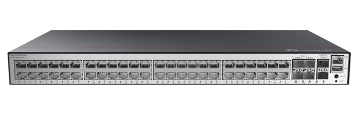

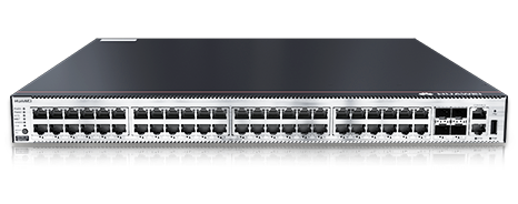
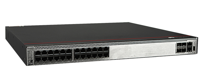
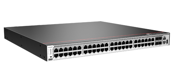
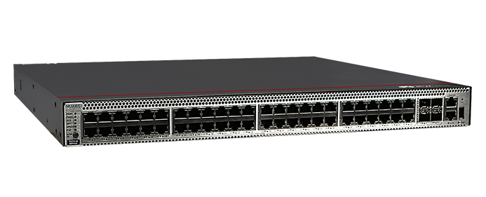
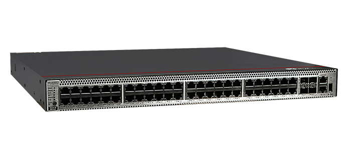

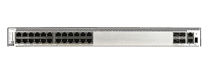
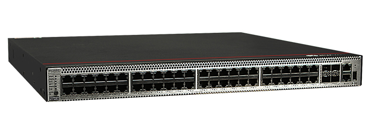


The Huawei S5731-S48P4X is a PoE (Power over Ethernet) switch featuring 48 Puerto 10/100/1000BASE-Ts and 4 10GE SFP+ ports. It supports two power module slots, each accommodating either a 1000 W or 600 W PoE power module, enabling flexible power configurations to meet various networking requirements.
▪ Port Configuration: The switch offers 48 Gigabit Ethernet ports for high-speed connectivity and 4 10-Gigabit SFP+ uplink ports, ensuring robust data transmission capabilities.
▪ PoE Support: With PoE+ capabilities, the S5731-S48P4X can deliver power to connected devices such as IP phones, wireless access points, and IP cameras, simplifying network deployment and reducing the need for additional power sources.
▪ Power Module Slots: The device includes two slots for power modules, allowing for the installation of either 1000 W or 600 W PoE power modules. This flexibility supports various power requirements and enhances the scalability of the network infrastructure.
▪ Cooling System: The switch is equipped with fan modules to maintain optimal operating temperatures. Compatible fan modules include the FAN-023A-B, which is a fan box designed for side exhaust.
INFO.
▪ Memory and Storage: The S5731-S48P4X comes with 2 GB of memory and a total of 1 GB flash memory, ensuring efficient performance and adequate storage for configurations and system files.
INFO.
▪ Optical Modules: The switch supports various optical modules for the 10GE SFP+ ports, providing flexibility in network design and implementation. Specific compatible optical modules can be found in Huawei's technical documentation.
INFO.
▪ Fan Modules: As mentioned, the FAN-023A-B is a compatible fan module, ensuring proper cooling and reliable operation of the switch.
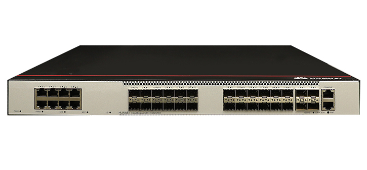
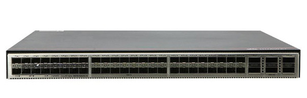
Huawei CloudEngine Switch S5731-S48P4X
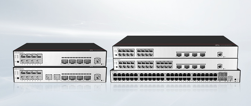
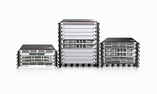
Huawei All serie Switches New and Used
For Huawei product list and quote, please visit: https://www.hi-network.com/categories/huawei or contact us at www.hi-network.com Re88pl99ace1 (Email: [email protected] (en inglés))
Table 4-1344 lists the mapping between the S5731-S48P4X chassis and software versions.


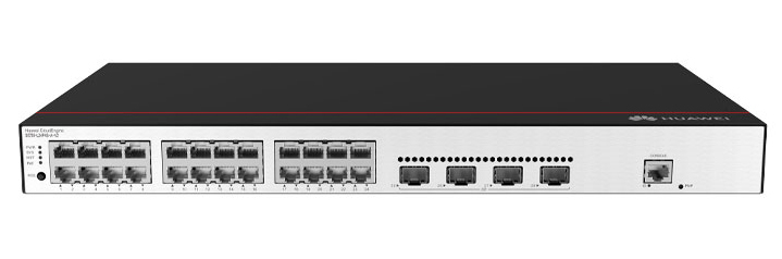
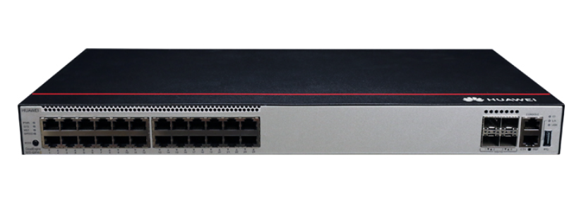
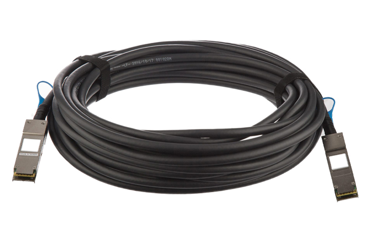
1 | Cuarenta y ocho puertos PoE+ 10/100/1000BASE-T | 2 | Cuatro puertos 10GE SFP+ Módulos y cables aplicables:
|
3 | Un puerto de consola | 4 | Una ti ti gestión puerto |
5 | Un puerto USB | 6 | Un botón de un PNP NOTICE: To restore the factory settings and reset the switch, hold down the button for at least 6 seconds. To reset the switch, press the button. Resetting the switch will cause service interruption. Exercise caution when you press the PNP button. |
7 | Tornillo de tierra Nota: It is used with a ground cable. | 8 | 1 Nota: Applicable fan module: FAN-023A-B (Fan Box (B, Fan Panel Side Exhaust)) |
9 | Ranura 2 para el módulo del ventilador Nota: Applicable fan module: FAN-023A-B (Fan Box (B, Fan Panel Side Exhaust)) | 10 | 1 Nota: Applicable power module:
|
11 | Ranura para módulo de potencia 2 Nota: Applicable power module:
| - | - |
10/100/1000BASE-T port
10GE SFP+ optical port
Puerto de consola
Gestión del puerto
Attribute | descripción |
|---|---|
Tipo de conector | RJ45 |
Standards compliance | IEEE802.3 |
Working Mode | 10/100 Mbit/s auto-sensing |
Maximum transmission distance | 100 m |
Puerto USB

USB flash drives from different vendors differ in model compatibility and drivers. If a USB flash drive cannot be used, try to replace it with another one from a mainstream vendor. Switches support a maximum of 128 GB USB flash drives.
Si el conmutador no tiene un archivo de configuración, el sistema intenta entrar al modo de inicio de sesión web. En este modo, el estado de los indicadores de modo es el siguiente:
Si el sistema entra en el modo de inicio de sesión web con éxito, todos los indicadores de modo se vuelven verdes y permanecen encendurante un máximo de 10 minutos.
Si el sistema no entra en el modo de inicio de sesión inicial, todos los indicadores de modo parpadean rápidamente durante 10 segundos y luego restauran el estado predeterminado.
Si el conmutador tiene un archivo de configuración, el sistema no puede entrar al modo de inicio de sesión web. En este caso, todos los indicadores de modo parpadeo rápido de 10s, y luego volver a los Estados por defecto.


No. | Indicator | nombre | Color Color Color Color | Estado de la situación | descripción |
|---|---|---|---|---|---|
1 | PWR1 | Indicador del módulo de potencia | - | fuera | Ningún módulo de alimentación está disponible en la ranran1 del módulo de alimentación, o el interruptor tiene sólo un módulo de alimentación, pero el módulo de alimentación No funciona normalmente. |
verde | Firme sobre | Un módulo de potencia está instalado en la rande módulo de potencia 1 y funciona normalmente. | |||
amarillo | Firme sobre | El conmutador tiene dos módulos de potencia instalados. Cualquiera de las siguientes situaciones ocurre en la ranura de módulo de potencia 1:
| |||
2 | PWR2 | Indicador del módulo de potencia | - | fuera | No hay módulo de alimentación disponible en la rande módulo de alimentación 2, o el interruptor tiene sólo un módulo de alimentación, pero el módulo de alimentación No funciona normalmente. |
verde | Firme sobre | Un módulo de potencia está instalado en la rande módulo de potencia 2 y funciona normalmente. | |||
amarillo | Firme sobre | El conmutador tiene dos módulos de potencia instalados. Cualquiera de las siguientes situaciones ocurre en la ranura de módulo de potencia 2:
| |||
3 | SYS | Indicador de estado del sistema | - | fuera | El sistema no está funcionando. |
verde | Parpadeo rápido | El sistema está arrancando. | |||
verde | Firme sobre | Durante la fase de preparación de la puesta en marcha del sistema, el indicador SYS es de color verde constante, que dura un máximo de 30 segundos. | |||
verde | Parintermitente lento | El sistema está funcionando normalmente. | |||
rojo | Firme sobre | El sistema no funciona normalmente después del registro, o se ha generado una alarma de ventilador o una alarma de temperatura. | |||
4 | El MST | Indicador de pila | - | fuera |
|
verde | Firme sobre | El modo pila está seleccionado. El conmutador es un conmutador standby o esclavo en una pila, y los indicadores de puerto de servicio muestran el identificde pila del conmutador. | |||
verde | parintermitente |
| |||
5 | velocidad | Indicador de velocidad | - | fuera | El modo velocidad no está seleccionado. |
verde | Firme sobre | Se selecciona el modo velocidad, y los indicadores de puerto de servicio muestran la velocidad de cada puerto. | |||
6 | PoE | Indicador PoE | - | fuera | El modo PoE no está seleccionado. |
verde | Firme sobre | Se selecciona el modo PoE, y los indicadores de puerto de servicio muestran el estado PoE de cada puerto. | |||
7 | MODE | Botón de interruptor de modo | - | - |
Si no pulsa el botón modo en 45 segundos, los indicadores del puerto de servicio volverán al modo predeterminado. En este caso, los indicadores de velocidad y PoE están apagados. |
ID | Indicador de identificación Nota: The mode switch button on the 02353AJH has an ID indicator. | - | fuera | El indicador ID no se utiliza (estado por defecto). | |
Azul azul | Firme sobre | El indicador identifica el interruptor a mantener. El indicador de identificación puede ser encendido o apagado remotamente para ayudar a los ingenieros de campo a encontrar el interruptor a mantener. | |||
8 | - | Indicador del puerto de servicio eléctrico (un indicador por puerto) | El indicador en la esquina superior izquierda de un puerto indica el indicador de un puerto en la parte superior, y el indicador en la esquina superior derecha indica el indicador de un puerto en la parte inferior. | Meanings of service port indicators vary in different modes. For details, see Table 4-1350 and Table 4-1351. | |
Indicador óptico del puerto de servicio (dos indicadores para cada puerto) | Cada puerto óptico tiene dos indicadores de un solo color. El de la izquierda es el indicador ACT (amarillo), yel de la derecha es el indicador LINK (verde). Las puntas de flecha muestran las posiciones de los puertos. Una punta de flecha hacia abajo indica un puerto en la parte inferior, y una punta de flecha hacia arriba indica un puerto en la parte superior. | ||||
9 | ETH | El indicador del puerto | - | fuera | El puerto ETH no está conectado. |
verde | Firme sobre | El puerto ETH está conectado. | |||
verde | parintermitente | El puerto ETH está enviando o recibiendo datos. | |||
10 | - | USB-based deployment indicator (en inglés) | - | fuera |
|
verde | Firme sobre | Un despliegue basado en USB se ha completado. | |||
verde | parintermitente | El sistema está leyendo datos de una unidad flash del USB. | |||
amarillo | Firme sobre | El conmutador ha copiado todos los archivos requeridos y completado la verificación de archivos. La unidad flash USB se puede quitar del interruptor. | |||
rojo | parintermitente | Se ha producido un error cuando el sistema está ejecutando el archivo de configuración o leyendo datos desde la unidad flash USB. | |||
Display Mode | Color | Estado de la situación | Description |
|---|---|---|---|
Default mode | - | fuera | El puerto no está conectado o ha sido apagado. |
verde | Firme sobre | Se ha establecido un enlace en el puerto. | |
verde | parintermitente | El puerto está enviando o recibiendo datos. | |
MST stack mode | verde | fuera | Port indicators do not show the stack ID of the switch. |
Firme sobre | El interruptor no es el interruptor maestro en una pila.
| ||
parintermitente | The switch is the master switch in a stack.
| ||
Speed mode | - | fuera | El puerto no está conectado o ha sido apagado. |
verde | Firme sobre | 10M/100M/1000M port: The port is operating at 10 Mbit/s or 100 Mbit/s. | |
verde | parintermitente | 10M/100M/1000M port: The port is operating at 1000 Mbit/s. | |
PoE mode | - | fuera | The port is not providing power to a powered device (PD). |
verde | Firme sobre | The port is providing power to a PD. | |
verde | parintermitente | The power of the PD connected to the port exceeds the power capacity of the port or the power threshold configured on the port. Alternatively, the PD does not comply with IEEE standards. |
Display Mode | Color | Estado de la situación | Description |
|---|---|---|---|
Default mode | - | fuera | El puerto no está conectado o ha sido apagado. |
verde | Firme sobre | Se ha establecido un enlace en el puerto. | |
amarillo | parintermitente | El puerto está enviando o recibiendo datos. | |
Speed mode | - | fuera | El puerto no está conectado o ha sido apagado. |
verde | Firme sobre | 1000M/10GE port: The port is operating at 1000 Mbit/s. | |
verde | parintermitente | 1000M/10GE port: The port is operating at 10 Gbit/s. 1000M port: The port is operating at 1000 Mbit/s. |
The switch is a PoE switch and supports two power module slots, each of which can have a 1000 W PoE or 600 W PoE power module installed. Pluggable AC and DC PoE power modules can be used together in the same switch.
Power Module 1 | Power Module 2 | Alimentación PoE disponible | Maximum Number of Ports (Fully Loaded) |
|---|---|---|---|
1000 W AC (220 V) 1000 W DC | - | 760 W |
|
1000 W AC (110 V) | - | 665 W |
|
1000 W AC (220 V) 1000 W DC | 1000 W AC (220 V) 1000 W DC | 1600 W |
|
1000 W AC (110 V) 1000 W DC | 1000 W AC (110 V) | Versions earlier than V200R021C10: 1330 W V200R021C10 and later versions: 1520 W |
|
600 W AC (220 V) | - | 380 W |
|
600 W AC (110 V) | - | 95 W |
|
600 W AC (220 V) | 600 W AC (220 V) | 950 W |
|
600 W AC (110 V) | 600 W AC (110 V) | 380 W |
|
1000 W AC (220 V) 1000 W DC | 600 W AC (220 V) | 1330 W |
|
When a switch has two power modules installed, the two power modules work in redundancy mode to provide power for the chassis and in load balancing mode to provide power for PDs.
The S5731-S48P4X uses pluggable fan modules for forced air cooling. Air flows in from the front side and exhausts from the rear panel.
This figure only shows the airflow direction and does not depict the actual device.
Table 4-1353 lists technical specifications of the S5731-S48P4X.
El artículo | Description |
|---|---|
Memoria (RAM) | 2 GB |
Flash | 1 GB en total. Para ver el tamaño de la memoria flash disponible, ejecute the Versión de visualizaciónRe88pl99ace1command. |
Tiempo medio entre fallas (MTBF) | 54, 96 años |
Tiempo medio de reparación (MTTR) | 2 horas |
disponibilidad | > 0.99999 |
Protección de puertos de servicio | Modo común: − 6 kV |
Protección contra aumento de tensión de la fuente de alimentación |
|
Dimensiones (H x W x D) |
|
Peso (con embalaje) | 8.8 kg (19.40 lb) |
Puertos de pila | Puertos 10GE SFP+ en el panel frontal |
RTC | apoyado |
RPS | No soport |
PoE | apoyado |
Rango de tensión nominal |
|
Rango de tensión máxima |
|
Consumo máximo de energía (100% de rendimiento, velocidad máxima de los ventiladores) |
|
Consumo típico de energía (30% de la carga de tráfico, probado según la norma ATIS) | 108 W |
Temperatura de funcionamiento | -5°C a +45°C (23°F a 113°F) a una altitud de 0-1800 m (0-5906 pies). Nota: Cuando la altitud es de 1800-5000 m (5906-16404 pies), la temperatura de operación más alta se reduce en 1°C (1,8 °F) cada vez que la altitud aumenta en 220 m (722 pies). El interruptor no se puede iniciar cuando la temperatura ambiente es inferior a 0°C (32°F). |
Temperatura de almacenamiento | -40°C a +70°C (-40°F a +158°F) |
Ruido a temperatura normal (27°C, potencia acústica) | < 62,3 dB(A) |
Humedad relativa | 5% a 95%, sin condensación |
Altitud de operación | 0-5000 m (0-16404 pies) |
certificación |
|
Número de pieza | 02353AJH 02353AJH-001 02353AJH-003 |
 Etiquetas calientes:
Huawei Switches
hot products
Etiquetas calientes:
Huawei Switches
hot products
Regístrepor correo electrónico ahora para acciones semanales de promoción
100% free, Unsubscribe any time!
Add 1: Room 605 6/F FA YUEN Commercial Building, 75-77 FA YUEN Street, Mongkok KL, HongKong Add 2: Room 405, Building E, MeiDu Building, Gong Shu District, Hangzhou City, Zhejiang Province, China
Whatsapp/Tel: +8618057156223 Tel: 0086 571 86729517 Tel en Hong Kong: 00852 66181601
Correo electrónico: [email protected]
 English
 Pусский
 Français
 Español
 Português